
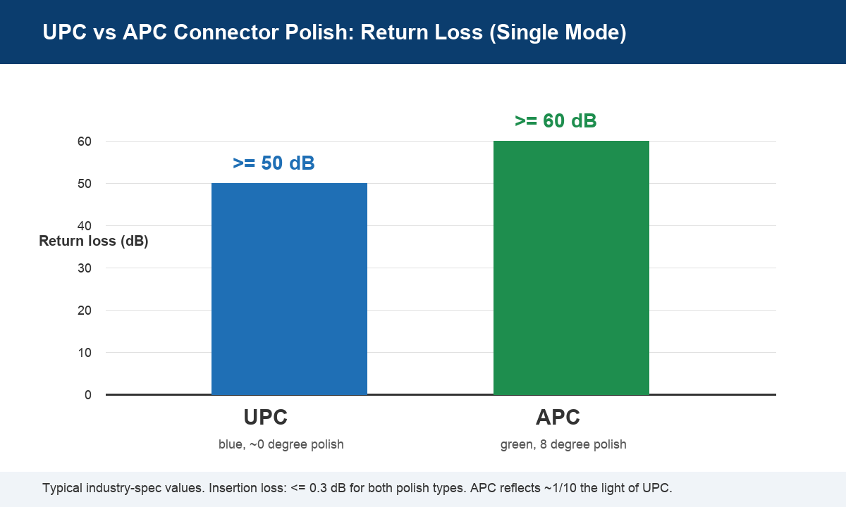
UPC vs APC is the first connector question most buyers face when ordering fiber optic patch cords, pigtails or field-installable connectors, and getting it wrong shows up as failed acceptance tests or noisy analog channels. The short answer: both polish types deliver excellent optical performance, but APC (Angled Physical Contact) reflects far less light back toward the transmitter — return loss of about 60 dB versus roughly 50 dB for UPC (Ultra Physical Contact) on single-mode links. That extra reflection margin matters in PON outside plant, DWDM and RF-over-fiber systems, while UPC costs less and remains perfectly adequate for most LAN, CCTV and short-reach links. This guide explains the geometry behind each polish, how to read the color codes, where the standards set return loss and insertion loss, and how to choose the right polish for your next order.
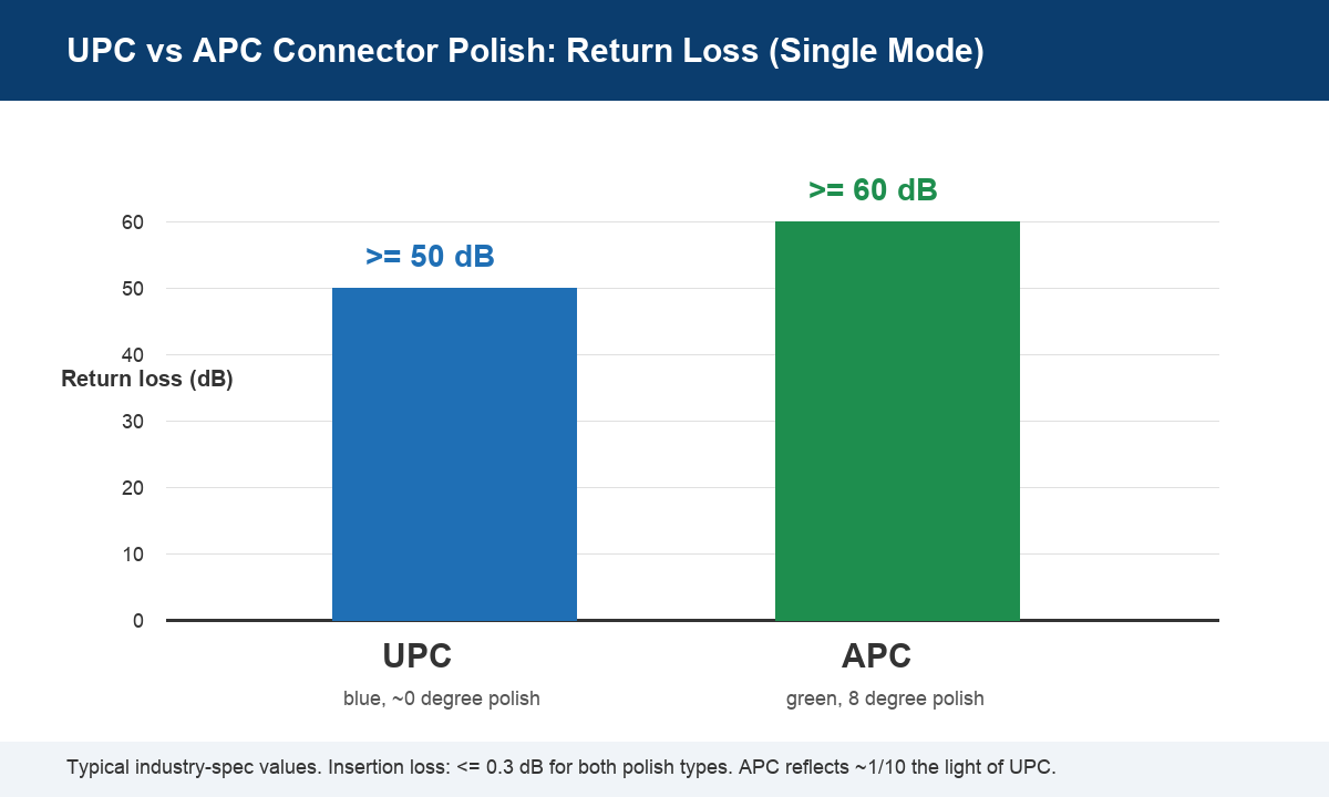
Table of Contents
- What the Polish Types Actually Mean
- UPC vs APC: Return Loss and Insertion Loss
- Why the APC Connector Is Green (and UPC Is Blue)
- When APC Wins in the UPC vs APC Trade-off
- When UPC Is Still the Better Buy
- Can You Mix UPC and APC in One Link?
- A Practical Checklist for Buyers
What UPC and APC Polish Actually Mean
Every single-mode connector endface is polished so the two mated ferrules touch over a small optical contact area — the principle behind all “physical contact” designs. The difference between the two polish types is purely geometric:
- UPC (Ultra Physical Contact): the ferrule endface is polished to a slightly domed, near-zero-degree surface. Light hits the glass-to-air interface straight on, so a small fraction of it reflects directly back down the core.
- APC (Angled Physical Contact): the ferrule endface is polished at an 8° angle. Reflected light is steered into the cladding wall instead of straight back toward the laser, which is why the APC connector achieves much higher return loss.
Both use the same zirconia ceramic ferrule, the same latching hardware and the same cable. The polish angle is essentially the only fundamental difference — yet once you understand it, the rest of the UPC vs APC comparison falls into place naturally, from color coding to pricing to which systems each polish belongs in. If you want a deeper background on connector families and ferrule standards, the optical fiber connector reference is a good neutral overview.
UPC vs APC: Return Loss and Insertion Loss
The metric that really separates the two polishes is return loss — how much light the mated pair reflects back toward the transmitter. In any UPC vs APC datasheet comparison, the numbers industry-standard test reports quote are:
| Parameter | UPC (single mode) | APC (single mode) |
|---|---|---|
| Polish angle | ~0° (domed) | 8° |
| Typical return loss | ≥ 50 dB | ≥ 60 dB |
| Typical insertion loss | ≤ 0.3 dB | ≤ 0.3 dB |
| Connector / ferrule color | Blue | Green |
| Typical applications | LAN, indoor FTTH, CCTV, data center | PON outside plant, DWDM, RF / analog video |
Read the return loss fiber numbers carefully: a 10 dB gap means an APC pair reflects roughly one-tenth of the light that a UPC pair reflects. For most digital links that extra margin is invisible at the receiver, but for analog transmission — RF over fiber, CATV overlay, high-precision DWDM — back-reflection creates noise directly in the signal path, and APC becomes close to mandatory. On multimode links, return loss requirements are much looser (commonly specified in the 20–35 dB range), which is one reason APC is almost never specified for multimode cable assemblies.
Insertion loss is far less differentiating. Both polishes are normally specified at ≤ 0.3 dB per mated pair, and in practice well-made APC pairs are often slightly more consistent because the angled contact is less sensitive to microscopic dust and endface gaps. If a supplier quotes dramatically different insertion loss between the two, the cause is workmanship, not the polish geometry. When you evaluate fiber optic patch cords, always ask for the per-batch IL/RL test data rather than the polish label alone.
Why the APC Connector Is Green (and UPC Is Blue)
Color is the fastest field check, and it is standardized: an APC connector is green — green boot, green zirconia ferrule, green adapter. UPC single mode is blue. Multimode connectors are beige or aqua and are essentially always UPC. The convention exists so installers can tell the two polishes apart at a glance, because the physical difference between them is invisible to the eye. Any UPC vs APC installation guide starts with this color rule for good reason.
Why does the color discipline matter so much? Because the 8° angle means an APC ferrule only makes edge contact with a flat UPC ferrule, leaving an air gap at the core. That gap can leak light, cause a multi-decibel insertion-loss spike and collapse return loss below specification. An APC connector that is green on the boot but mated against a blue UPC port is the single most common cause of “new link, terrible loss” service calls — always match polish to polish, end to end.
When APC Wins the UPC vs APC Trade-off
Specify APC when back-reflection is genuinely a problem for the system — these are the cases where the UPC vs APC debate resolves itself in favor of the green connector:
- GPON / XGS-PON outside plant: most telecom operators standardize on green SC/APC for splitters, distribution closures and drops, because the ODN is passive and any reflection returns to the OLT port for its entire life.
- DWDM and CWDM links: dense channel spacing makes reflected light interfere with adjacent wavelengths; operators demand ≥ 60 dB return loss on the connectors.
- RF over fiber and analog video: analog signals are far more sensitive to reflection-induced noise than digital ones.
- Any green-port equipment: if the OLT, splitter or transceiver port is already APC, the patch cords must be APC — the equipment decides.
When UPC Is Still the Better Buy
In the UPC vs APC trade-off, UPC wins on cost, availability and compatibility with the installed base. Choose UPC when the link genuinely does not need APC’s reflection margin:
- The link is digital and short: enterprise LANs, CCTV backhauls, campus backbones and data center interconnects tolerate 50 dB return loss with no measurable penalty.
- The equipment ports are blue/UPC: most ONTs, media converters and Ethernet switches use UPC interfaces; matching them keeps spares interchangeable.
- Multimode runs: OM3/OM4/OM5 patching is UPC by convention across the industry.
- Budget matters at scale: for large indoor FTTH segments or machine-room patching, the per-piece saving on thousands of UPC assemblies adds up, with no performance downside for the application.
A practical pattern seen in many FTTH builds: APC throughout the outside plant (OLT to splitter to drop closure), then a single UPC-to-APC decision point at the socket, with everything indoors kept UPC. Whatever pattern you pick, keep it consistent — mixed polishes hidden inside one link are the failure case, not either polish itself.
Can You Mix UPC and APC in One Link?
No — and this is worth repeating because it is the most common field mistake in the whole UPC vs APC topic. Directly mating a UPC ferrule to an APC ferrule leaves an air gap over most of the core: insertion loss can jump by several decibels and return loss can fall to 20–30 dB or worse, silently undoing the reason you bought APC in the first place. Hybrid adapters exist for bench testing and temporary troubleshooting, but they should never be left in a permanent link. The correct fix is always to replace the wrong-polish assembly, not to adapt around it. If your crews carry both types, make the green-vs-blue check part of the installation routine — it takes two seconds and prevents the majority of polish-related faults.
A Practical Checklist for Buyers
Before issuing a purchase order, settle the UPC vs APC question with four checks:
- Follow the equipment. The ports on your OLT, splitter, ONT and transceivers fix the polish for every assembly that touches them. Green ports = APC, blue ports = UPC.
- Follow the operator standard. If you are building to a carrier’s ODN specification, it will state the polish explicitly; do not deviate for stock reasons.
- Keep each link uniform. One polish from end to end, including pigtails inside splice trays and the connectors on test jumpers.
- Demand IL/RL test reports. Polish type alone is not a quality guarantee; per-batch 100% IL/RL testing is what separates good assemblies from cheap ones.
Getting these four right resolves almost every UPC vs APC dispute before hardware ships — and they cost nothing to apply at order time, while fixing them after installation means truck rolls. Treat the UPC vs APC choice as a design decision, not a catalog checkbox, and your links will pass acceptance the first time. In short: UPC vs APC is decided by your equipment ports, your operator’s standard and your application’s tolerance for back-reflection — never by whatever is left in the spares box.
Bottom Line: Order the Right Polish Once
Most connector problems trace back to the ordering stage, not the field. Decide the polish per segment based on equipment ports and system type, color-check every assembly at the tray, and buy from a supplier that tests every patch cord. PNA’s fiber optic patch cord and pigtail range covers SC, LC, FC and ST in both UPC and APC, each assembly tested for insertion loss and return loss before packing. For FTTH drop and indoor terminations where splicing crews are scarce, our fiber optic fast connectors are also available in both polishes for tool-free field installation. If you are unsure which mix fits your project, send us your link design and our engineers will recommend the right polish per segment — usually within one working day.