
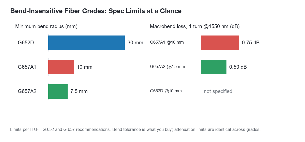
G657A1 vs G652D is the comparison that decides most FTTH and in-building fiber bills of materials. Choose G657A1 wherever installers handle fiber by hand — drops, risers, patch cords — because it tolerates a 10 mm bend radius. Keep G652D for engineered outside-plant routes, where controlled bends and the lowest cost per metre win. Add G657A2 only when geometry forces a 7.5 mm bend inside compact enclosures. All three share identical attenuation limits; what you buy with G657 is bend tolerance, not lower loss.
Table of Contents
- What Each Grade Actually Specifies
- G657A1 vs G652D: The Numbers That Matter
- Where Bend-Insensitive Fiber Earns Its Premium
- Where G652D Is Still the Right Call
- Compatibility: Splicing, Connectors and Mixing Grades
- G657A1 vs G652D in Practice: A Selection Checklist
- Common Specification Mistakes
- Frequently Asked Questions
What Each Grade Actually Specifies
The three designations come from two different ITU-T recommendations, which is the source of most confusion in tender documents. G652D is a standard single-mode fiber defined in G.652. G657A1 and G657A2 are bend-insensitive fibers defined in the ITU-T G.657 recommendation, and both are designed to coexist with G652D in the same network rather than replace it. That coexistence is deliberate: the G657A1 vs G652D pairing was engineered for compatibility from the start.
G652D: the low-water-peak baseline
G652D is the workhorse single-mode fiber. The “D” suffix means low water peak, so the fiber is usable across the full 1260–1625 nm window instead of carrying a hydroxyl absorption bump around 1383 nm. Standard limits are an attenuation of no more than 0.35 dB/km at 1310 nm and 0.20 dB/km at 1550 nm, with a mode field diameter in the 8.6–9.5 µm range at 1310 nm.
What G652D does not promise is tight-bend performance. Routine handling assumes bend radii in the 30 mm region under load, and a careless 10 mm bend in a patch panel can cost tenths of a dB. In a long feeder span that is irrelevant; in a rack with 144 cords dressed into a shallow manager, it is the difference between a clean link budget and a trouble ticket.
G657A1: the 10 mm class
G657A1 is the entry point to bend-insensitive fiber. It is specified for a 10 mm bend radius, with macrobend loss at 1550 nm held to roughly 0.75 dB for one turn at that radius, and better figures at 1625 nm. Crucially, its mode field diameter and cable cut-off are kept compatible with G652D, so you can splice A1 into an existing G652D plant without a splice-loss penalty.
For most FTTH and in-building work, A1 is the sensible default. It survives the bends real installers make — around a corner in a riser, behind a wall socket, looped inside a small termination box — without the premium attached to the tighter grades.
G657A2: the 7.5 mm class
G657A2 tightens the requirement to a 7.5 mm bend radius, with macrobend loss around 0.5 dB for one turn at 1550 nm. This is the grade for places where a 10 mm loop will not fit: shallow wall boxes, compact ONT enclosures, dense patching where cords fold back on themselves.
A2 remains splice-compatible with G652D in practice, but the glass design is more heavily modified, so confirm mode field diameter on the datasheet rather than assuming. For runs measured in metres the risk is negligible; for anything approaching a long span, A1 or G652D is the better engineering choice. This is also why G657A1 vs G652D pricing differs only modestly, while A2 sits visibly higher.
G657A1 vs G652D: The Numbers That Matter
The table below reflects ITU-T specification limits and typical catalogue values. Treat the attenuation figures as limits to specify, not as measured performance guarantees for a particular reel.
| Parameter | G652D | G657A1 | G657A2 |
|---|---|---|---|
| Bend radius, specification | ~30 mm (handling) | 10 mm | 7.5 mm |
| Macrobend loss, 1 turn @1550 nm | Not specified at 10 mm | ≤0.75 dB @10 mm | ≤0.50 dB @7.5 mm |
| Attenuation @1310 nm | ≤0.35 dB/km | ≤0.35 dB/km | ≤0.35 dB/km |
| Attenuation @1550 nm | ≤0.20 dB/km | ≤0.20 dB/km | ≤0.20 dB/km |
| Mode field diameter @1310 nm | 8.6–9.5 µm | 8.6–9.5 µm | 8.6–9.5 µm |
| Relative cost per metre | Baseline | Small premium | Larger premium |
| Typical use | Feeder, backbone | Drop, riser, cord | Tight boxes |
Reading G657A1 vs G652D row by row settles most procurement debates. Attenuation limits are identical, so nobody is buying lower loss by moving to G657 — they are buying bend tolerance. The price premium for A1 is modest and predictable, while A2 carries a noticeably higher per-metre cost that only pays off where geometry demands it.
Where Bend-Insensitive Fiber Earns Its Premium
FTTH drops and in-home routing
Drop cable is where bend-insensitive glass paid for itself first. A drop leaves an aerial span or buried duct, enters the building, turns through a wall penetration and terminates at a socket — often with two or three tight bends inside a metre. That is why G657A1 vs G652D is barely a debate for drops: most pre-connectorized drop cable on the market is built on A1 glass.
Patch cords and high-density frames
In a high-density frame, cords are dressed into vertical managers and folded back into adjacent ports. A G652D cord can be pushed to a bend radius it was never designed for during routine moves, adds and changes. Bend-insensitive cordage — A1 for general use, A2 where the manager is shallow — keeps those moves from becoming intermittent faults. Our fiber optic patch cord and pigtail assemblies are available on both grades.
Field termination and small enclosures
Where installers terminate on site, the fiber has to tolerate being coiled into whatever the enclosure offers. Bend-insensitive glass plus a mechanical termination point is exactly where fiber optic fast connectors are used, and where A1 glass cuts rework on first-time installs.
Where G652D Is Still the Right Call
It is a mistake to read bend-insensitive fiber as a universal upgrade. On feeder and backbone routes, cable sits in ducts, trays or on strand with controlled bend radii, and fiber is spliced in closures built for the purpose. There, the macrobend advantage of G657 delivers nothing measurable, while the per-metre premium is multiplied across tens of kilometres. In other words, G657A1 vs G652D is not an either-or decision; most networks run both.
A common and sound hybrid design uses G652D on the feeder, G657A1 from the distribution point to the subscriber, and G657A2 only inside the premises. Splicing between grades is routine.
Compatibility: Splicing, Connectors and Mixing Grades
Splicing G657A1 vs G652D: mode field diameter decides
Because all three grades sit in the same 8.6–9.5 µm mode field window, fusion splicing G657A1 to G652D normally produces losses indistinguishable from same-grade splicing. G657A2 is also widely compatible, but its tighter glass design means you should ask for the MFD figure and splice a trial batch before committing on a large project.
Connector and polish decisions are separate
Fiber grade says nothing about connector polish or endface quality. A bend-insensitive cord with a poor endface will still fail. Specify insertion loss and return loss separately, match polish type at both ends, and inspect a sample of endfaces on arrival.
G657A1 vs G652D in Practice: A Selection Checklist
- Map the geometry first. Walk the route and find the tightest bend. Nothing below about 15 mm means G652D or A1 is sufficient; shallow boxes mean A2.
- Segment the bill of materials. There is no requirement to use one grade project-wide; deciding G657A1 vs G652D per segment — feeder, drop, cordage — usually costs less than one grade everywhere.
- State the ITU-T grade in the PO. Writing “G657A1 vs G652D vs G657A2 — select by section” beats “bend-insensitive fiber”, which a supplier can quote with any grade.
- Ask for macrobend test data. Require the 10 mm or 7.5 mm, one-turn, 1550 nm and 1625 nm results, not just attenuation at 1310/1550 nm.
- Confirm MFD and cut-off wavelength when mixing grades in one link, especially with A2.
- Check cable construction too. Bend-insensitive glass in a stiff jacket still kinks; the sheath and strength member decide field behaviour.
Common Specification Mistakes
The most frequent error is writing G657 into a tender without the suffix, leaving grade selection to whoever quotes. A tender that leaves G657A1 vs G652D undefined invites the wrong grade at the wrong price. The second error is assuming A2 is “better” and specifying it everywhere, paying a premium on feeder cable that will never see a 7.5 mm bend. The third is the reverse: using G652D cordage in dense patching to save cents per cord, then absorbing the cost in maintenance visits.
A quieter mistake is mixing grades without documenting it. Five years later a technician replaces a damaged drop and nobody knows whether the original was A1 or A2. Record the grade on the as-built drawing alongside the cable type.
Frequently Asked Questions
Can I splice G657A1 directly to G652D?
Yes. G657A1 was designed for compatibility with G652D, and field splice losses are normally comparable to same-grade splicing. Verify with the splicer’s estimated loss and a sample OTDR trace on the first closures.
In the G657A1 vs G652D choice, which grade belongs in patch cords?
A1 for general patching. G652D is acceptable where managers are deep and cords are long, but A1 removes an entire class of bend faults in dense fields for a small per-cord premium.
Does bend-insensitive fiber improve link budget on long spans?
Not meaningfully. Attenuation limits match G652D. The gain is bend tolerance and installation robustness, which affects yield and maintenance rather than span reach.
Choosing With Confidence
G657A1 vs G652D reduces, in practice, to a simple rule: G652D where the route is engineered and the distance is long, G657A1 wherever installers handle fiber by hand, and G657A2 only where the physical space dictates a 7.5 mm bend. Specify the grade explicitly, segment the bill of materials, and ask for macrobend test data — that prevents nearly every problem this choice can cause.
Building a bill of materials for an FTTH or in-building project? Review our fiber optic patch cord and pigtail range or our FTTH solutions, and talk to our team about grade selection matched to your route and enclosure plan.