1. Introduction
The 3GPP protocol stipulates that 5G base station types can be divided into FR1sub6G band and FR2 band (24.24GHz~52.6GHz) according to the frequency band. As 3GPP release 21 will formulate 6G technical standard specifications, new spectrum resources will be introduced to meet the demand for tight spectrum resources.
As the number of frequency bands increases, the density of wireless base station construction is also increasing. The interference problems between base stations are increasing.
In order to better simulate the actual co-site base station environment, ITU-⋅R and RF conformance standard TS38.141-2 respectively provide recommendations for air interface spurious testing of 5G base stations and define corresponding OTA test standards. Currently, the anechoic chambers suitable for base station spurious testing include compact field or reverberation chamber .
Reverberation chambers are suitable for testing in multipath environments, but their strong multipath and reflection effects make it difficult to obtain ideal, interference-free test results, limiting the accuracy of high-frequency testing. Compact test ranges provide a reflection-free, interference-free electromagnetic environment. Whether in a reverberation chamber or a compact test range, electromagnetic waves experience varying degrees of attenuation in space.
For co-site spurious emissions, the actual spurious levels can far exceed the specified level. This article addresses the problem of actual signals being too small for accurate spectrum analyzer measurement by adding high-gain amplifiers and filtering modules.
2. Base station air interface spurious emission test standards
The primary purpose of spurious emission testing is to measure the impact of the maximum power carrier signal emitted by a mobile base station on the uplink frequency band of other co-located base stations (such as GSM, WCDMA, NR, and E-UTRA base stations). Relevant standards include international specifications such as 3GPP, FCC, ETSIEN, and CISPR.
These standards define spurious emission limits and test environment specifications for devices operating outside of specific frequency bands. Rigorous testing helps verify the electromagnetic compatibility and coexistence capabilities of devices, ensuring compliance with regulations under co-located conditions.
According to the definition of spurious emissions in Section 6.7.5 of Section 38.141-2 of the 3GPP Air Interface Radio Frequency Test Protocol, mobile base station spurious emissions include general spurious emissions, co-existence spurious emissions, and co-location spurious emissions.
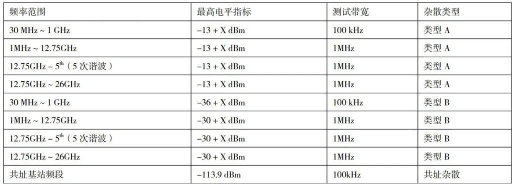
General spurious emissions cover the 30 MHz to 26 GHz frequency band. Table 1 shows the spurious emission specifications. For Type A, the upper power amplitude limit is -13 + X dBm. For Type B, the upper power amplitude limit is -36 dBm from 30 MHz to 1 GHz and 30 + X dBm from 1 GHz to 26 GHz. Both types can be tested using a conventional spectrum analyzer in a compact test chamber or reverberation chamber.
However, when testing co-site spurious emissions, the maximum level requirement is -113.9 dBm, making the test more stringent. This places high demands on both the test solution and the dynamic range and noise floor of the frequency analyzer.
3. Air Interface Spurious Test Solution
(1) General spurious test scheme for reverberation chamber
The reverberation chamber is a shielded chamber with large dimensions and highly conductive reflective walls. It consists of a lifting turntable, rotating blades, a reference antenna, a receiving antenna, and reflective walls.
The swing of the rotating blades changes the boundary conditions of the chamber, thereby forming a statistically uniform, isotropic, and randomly polarized electromagnetic environment in the chamber, so that a large amount of uncorrelated sampling data can be obtained.
A major advantage of the reverberation chamber is its high space utilization, good repeatability and stability. A well-stirred reverberation chamber can measure TRP very stably. The formula for calculating TRP in a reverberation chamber is as follows:
Where η is the base station integrated antenna radiation efficiency, M
1 (r) is the mismatch coefficient, P
(r) is the normalized power value, and P
BS is defined as follows:

U BS is the voltage measured when the base station receives data when the radio is turned on. The TRP value is obtained by averaging multiple uncorrelated samples collected in the reverberation chamber. The reverberation chamber used for this experiment’s universal spurious test measures dimensions of 4.43m (L) × 3.34m (W) × 52.91m (H).
According to the free space propagation loss formula:
F is the frequency, and D is the test distance. Higher frequencies and longer distances result in greater loss. Assuming F = 3.5 GHz, EIRP = 77 dBm, D = 1 m, and OSS = -43.33 dB, the actual received power is 33.67 dBm. The FSW26 instrument’s noise floor, without preamplifier, is approximately -159 dBm/Hz. Normalized to 1 MHz, the instrument’s typical noise floor is 99 dBm/1 MHz. Based on air interface loss, the final noise floor is 54.67 dBm/1 MHz.
According to the test standards mentioned in Section 2, the instrument fully meets the 3GPP spurious emission test requirements for conventional test types A and B. When testing co-site spurious emissions (maximum level specification -113.9 dBm), a spectrum analyzer with a low noise floor is required.
Under the above test conditions, the spectrum analyzer noise floor, normalized to 100kHz, is -109dBm/100kHz. With the instrument preamplifier enabled, the final noise floor is around -120dBm/100kHz. In actual over-the-air testing, the instrument noise floor is -120dBm/100kHz + 43.33dB, or -76.67dBm/100kHz.
Taking path loss and measurement margin into account, the spectrum analyzer noise floor in actual testing is greater than -76.67dBm/100kHz. Using a radio reverberation chamber test solution would make it difficult to accurately measure co-site spurious emissions (-113.9dBm/100kHz).
(2) CATR air interface co-site spurious emission test solution
The compact range uses a parabolic reflector to convert the spherical waves emitted by the antenna under test into quasi-plane waves, simulating far-field conditions. The entire space is covered with absorbing materials to minimize the reflection of electromagnetic waves and provide an interference-free test environment for stray emissions.
It scans the EIRP of several points on a spherical surface and calculates the TRP value according to the formula. The spherical Cartesian coordinates of the antenna integrated base station are defined as follows:

EIRP (θ n , ϕ m ) This is the equivalent isotropically radiated power at discrete points (θ n , ϕ m ).
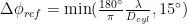
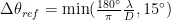
It represents the radiation intensity of the antenna in these specific directions. Here, it is assumed that the reference angular steps Δϕ ref and Δθ ref cannot be less than 15 ∘ .
When the diameter is less than about four wavelengths, the 15 ∘ step is given by formula (5-6)
As can be seen from the above formula, using fine resolution to scan the entire sphere will result in a more accurate TRP value, but this will take a lot of time and seriously affect test efficiency. According to formula (3), the free space loss in the 3.5GHz band is close to 43.33dB.
Even with an external amplifier module, it is difficult to accurately measure the result using a spectrum analyzer. This experiment follows the requirements of 3GPP section 6.7.5.5 and tests the CLTA (Co-Location Test Antenna) at seven locations. The CATR used is 10.66m (L) × 7.67m (W) × 5.08m (H) in size, and the frequency band ranges from 0.69GHz to 6GHz.
According to the DNAL formula: Pnoise = -174dBm/Hz + NF + (NF-1) / Gain, it can be seen that an external LNA does not reduce the instrument’s noise floor or increase its dynamic range. If the LNA has a poor noise figure, it will actually increase the instrument’s DNAL.
However, at the instrument’s lower noise floor limit, an external LNA can reduce the instrument’s noise floor within the dynamic range. Colocation spurious testing utilizes a duplexer and a high-gain amplifier with low noise figure.
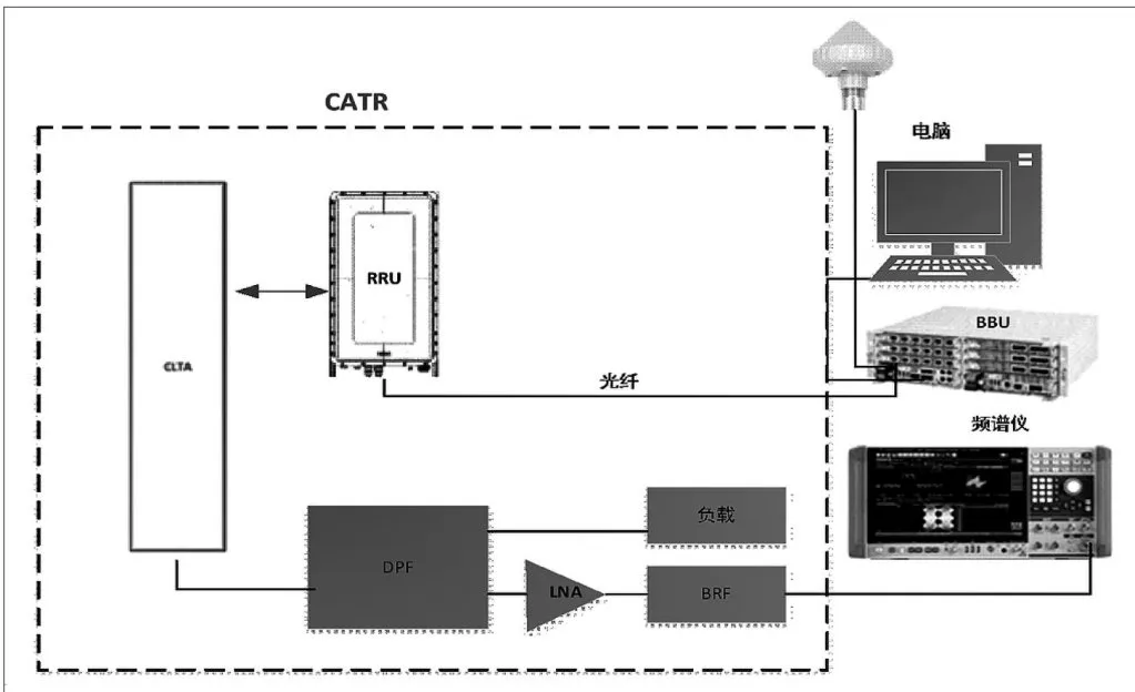
The high-rejection duplexer covers the n78 frequency range (3.4GHz to 3.8GHz). As shown in Figure 1, a conducted test method is used, connecting the antenna port to the RF coaxial line. The duplexer then splits the output signal into two, passing through the TX passband link port and being absorbed by the load.
The RX band-stop link carrier signal is suppressed by -80dBc before passing through an LNA (0.1GHz to 6GHz, 30dB gain, 1.2dB NF) and then connected to a band-stop filter. Finally, testing is performed using a spectrum analyzer.
At this point, with the instrument preamp disabled and an external LNA connected, the maximum instrument noise floor is -159dBm/Hz + 1.2dB, or -107.8dBm/100kHz. Assuming a 5dB insertion loss and 5dB line loss on the duplexer, or an ATT of approximately 5dB, the spectrum analyzer noise floor is -97dBm/100kHz.
With the external LNA connected, the instrument’s final noise floor is -107.8dBm/100kHz. With the instrument preamp enabled, the noise floor is approximately -120dBm/100kHz, allowing measurements down to -113.9dBm/100kHz.
Therefore, the test plan meets the requirements. In actual testing, dynamic ATT adjustment and the use of a gain-limited LNA are possible. As long as the ATT is less than the LNA gain, the noise floor can be adjusted within the dynamic range.
3.Out-of-band spurious emission data analysis
Comparison of measured data between the reverberation chamber and the compact field test indicates that test accuracy and selection of appropriate test methods significantly impact test results. The reverberation chamber can rapidly test common spurious and co-site spurious requirements, while the compact field test can maximize the provision of co-site spurious testing in an interference-free environment.
However, the multipath effect of electromagnetic waves in free space cannot meet the actual spurious requirements according to the reverberation chamber test method.
The only way to solve the problem of insufficient background noise within the dynamic range of the spectrum analyzer is to use duplexers, low-noise amplifiers, and filters.
4.Conclusion
Experimental test results show OTA spurious emission tests using a reverberation chamber and a compact range test.
A reverberation chamber can simulate complex multipath propagation environments in a relatively small space, making it suitable for general spurious and co-site spurious emission tests with lower performance requirements.
However, a reverberation chamber cannot simulate the long-range characteristics of free space and cannot provide high-precision directional testing. Compared to a reverberation chamber, a compact range test can simulate far-field characteristics and provide high-precision directional testing. However, the test air interface attenuation is significant, increasing the noise floor of the spectrum analyzer.
External duplexers, high-gain, low-noise-figure LNAs, and filters can be used to reduce the noise floor within the dynamic range of the spectrum analyzer. Compared to conducted testing, environmental variations and device performance directly affect test results.
Furthermore, lower spurious emission requirements place higher demands on the dynamic range and noise floor of the spectrum analyzer. However, when testing co-site spurious emission, antennas must be changed for different receive bands, reducing test efficiency. Providing a multi-band integrated antenna would significantly increase test efficiency.
Test the receive antenna power level by placing the antenna in different positions.