
Once the optical fiber cable is dug up or broken, it will cause a fatal blow to the business. So how to judge the cause of the failure? We can try to analyze it according to the picture.
1. Distance judgment
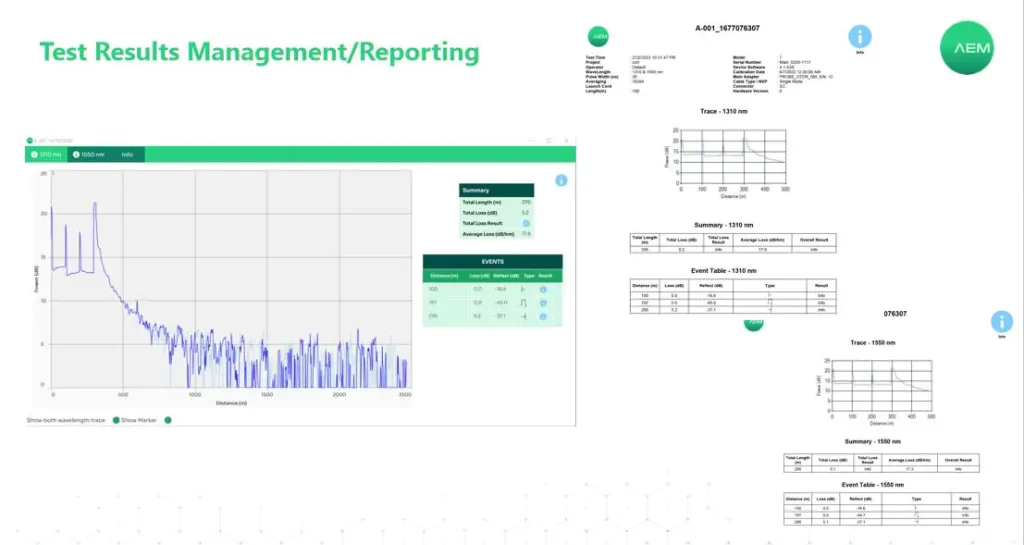
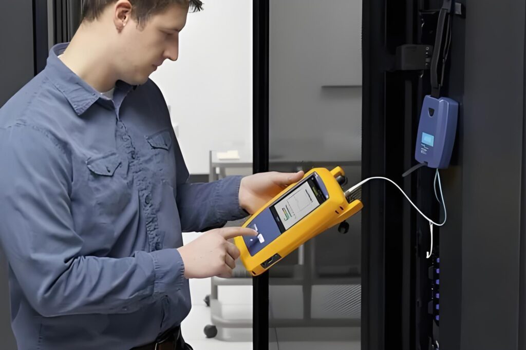
When the computer room determines that the fault is an optical cable line fault, the line maintenance department should test the faulty optical cable line in the computer room as soon as possible, and use OTDR to determine the location of the line fault point. The OTDR tester can be tested at a single end and can be operated in the computer room. Common OTDR brands include FLUKE, EXFO and other foreign brands, and there are many domestic brands, which can be purchased according to needs.
1.1 Example of AEM OTDR Optical Time Domain Reflectometer
AEM adapts to the needs of trial production, and launches a new generation of OTDR optical time domain reflectometer, with a very small blind area and large dynamic range, and supports fault location and loss testing of local area network and metropolitan area network optical cables. Let’s take a look at the new generation of AEM OTDR.
The following is the introduction in English, please refer to it as appropriate.
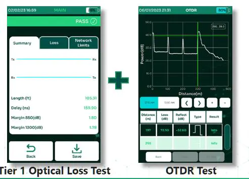
Tier 1 – Optical Loss Testing
Tier 1 Certification – Optical Loss Testing
In its simplest form and optical loss testing is a comparison between the optical power measured in dBm at the output of the light source and the power measured at the far end of a fiber connected to that same light source. The difference is known as loss or attenuation, expressed in dB.
Combining the light source/power meter, measuring against standards and providing a pass/fail is known as an Optical Loss Test Set.
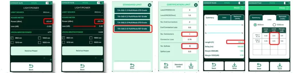
Tier 2 testing
TIA-568: Optical Fiber Cabling and Components Standard
Tier 2 testing supplements Tier 1 testing with the addition of an OTDR characterization of the eleme nts along the fiber cabling.
Simply put, Tier 2 is just testing the same fiber with an OLTS and an OTDR and documenting the resul ts of both.
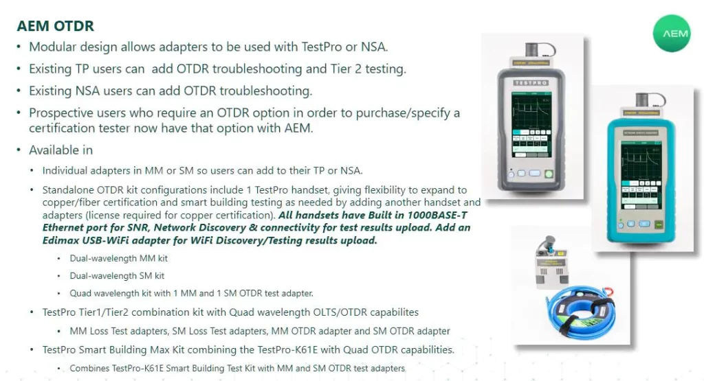
AEM OTDR Specifications
Available wavelengths
MM 850nm/1300nm
SM 1310nm/1550nm
Event dead zone
0.5m to 0.7 depending on wavelength
Attenuation dead zone
2.5m to 4.5m depending on wavelength
Dynamic Range
25dB @ 850nm / 27dB @1300nm
29dB @1310nm / 27dB @1550nm
Distance Measurement Range
9km for 850nm, 35km for 1300nm
80km for 1310nm, 130km for 1550nm
Pulse Width
3, 5, 10, 15,…, 24995, 25000 nsec
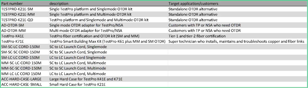
Individual adapters AD-OTDR-SM/AD-OTDR-MM are boxed and include 1 each of:
SC interface
2m SC-SC TRC (“connector protectors”)
LC & SC coupler
1.25mm & 2.5mm connector cleaners
AEM OTDR Optical Time Domain Reflectometer
Standalone OTDR kits/combination kits K21E/K41E/K71E include a hard case.
Launch cords are included ONLY with the Tier 1/Tier 2 combination kit K41E and the Smart Building Ma x kit K71E and must be purchased separately for all other configurations.
2. Possible reason estimation
According to the OTDR test display curve, the cause of the failure is initially determined, and the fault is dealt with in a targeted manner. According to the fault analysis, there are many problems in the connector box for optical cable failure caused by non-external forces. The reasons for fiber breakage or increase attenuation in the connector box are divided into the following situations:
(1) The optical fiber in the fiber disk is loose, causing the optical fiber to bounce up and squeezed at the edge of the fiber disk or the screw on the disk. In serious cases, the optical fiber will be crushed and broken.
(2) The residual fiber in the connector box is placed in a low local bending radius or the optical fiber twisting is seriously, resulting in large bending loss and static fatigue. The change in the 1310nm wavelength test is not obvious, and the loss of the 1550nm wavelength test connector is significantly increased.
(3) When making the end face of the optical fiber, the bare optical fiber is too long or the protection position of the optical fiber is improper when the heat shrink protection tube is heated, causing some of the bare optical fiber to be outside the protection tube, and the joint box will cause the bare optical fiber to break when the joint box is under external forces.
(4) When the coating is peeled off, the bare optical fiber is injured, and the damage expands after a long time. The loss of the joint increases with the severe case, the fiber will be broken.
(5) Due to the tight fixation of the optical cable, the displacement of the optical cable due to stress or the influence of external forces leads to the distortion or bending of the optical fiber, resulting in the attenuation of the optical fiber.
(6) Water enters the connector box, and the ice in winter leads to an increase in optical fiber loss, and even fiber breakage occurs.
3. Find the specific location of the fault point of the optical cable line
When the optical cable line is blocked due to obvious external forces such as natural disasters or external construction, the repair personnel carefully inspect along the optical cable line according to the fault phenomenon and the approximate fault location provided by the tester, and it is generally easier to find the fault location. If it is not the above situation, it is not easy for inspectors to find the location of failure from the abnormal phenomenon on the route. At this time, it is necessary to check with the original test data according to the distance between the fault point measured by OTDR and the test end to find out which two standard stones (or two connectors) the fault point is, and find the specific location of the fault point after the necessary conversion. If conditions permit, a two-way test can be carried out, which is more conducive to accurately judging the specific location of the fault point.
4. The main reasons that affect the accurate judgment of the obstacle points of optical cable lines
(1) There is an inherent deviation in OTDR
The inherent deviation of OTDR is mainly reflected in the distance resolution. Different test distance deviations are different. In the 150km test range, the test error reaches ±40m.
(2) Errors caused by improper operation of the test instrument
In the optical cable fault location test, the correctness of OTDR is directly related to the accuracy of the obstacle test. For example, factors such as improper setting of instrument parameters or inaccurate cursor setting will lead to errors in the test results.
(3) Calculation error
The fault point distance measured by OTDR can only be the length of the optical fiber, and the skin length of the optical cable and the ground distance from the test point to the obstacle point cannot be directly obtained. It can only be obtained through calculation. In the calculation, because the value cannot be completely consistent with the actual situation or the shrinkage rate of the optical cable used is not clear, a certain error will also occur. .
(4) Error caused by inaccurate completion data of optical cable lines
Due to the lack of attention to the accumulated data or the low credibility of the recorded data in the line construction, the completion data of the line are inconsistent with the actual data. Based on such data, it is impossible to accurately determine the obstacle point.
For example, when the optical cable is connected, the retention length of the residual fiber in the connector box, the retention length of the optical cable at various special points, and the change of the optical cable with the ups and downs of the terrain. The accuracy of these factors directly affects the positioning accuracy of the obstacle point.
5. After finding the location, the on-site investigation must be careful. If the optical cable is dug up, broken or bitten by small animals, the optical fiber welding machine can be used to connect the optical cable. The use of optical fiber welding machine and OTDR tester requires certain technical knowledge. Shenzhen Weixin Instrument specializes in various cable optical fiber. Tester sales, maintenance, leasing, calibration and other businesses. If you have cables and optical cables that are not smooth, you can contact us to provide on-site inspection and maintenance services.