Communication fiber optic cables are the backbone of modern telecommunication networks, enabling high-speed data transmission over long distances. However, these cables are susceptible to various faults that can disrupt communication services and lead to significant economic losses. In this article, we will explore the most common faults in fiber optic cables, their causes, and effective repair methods.

- Cable Breaks and Cuts One of the most common and severe faults in fiber optic cables is a complete break or cut in the cable. These faults can be caused by various factors, including construction activities, natural disasters (such as earthquakes or hurricanes), vandalism, or accidental damage during maintenance or installation. Cable breaks and cuts result in a complete loss of signal transmission, rendering the affected cable section useless.
- Repairing these faults typically involves the following steps:
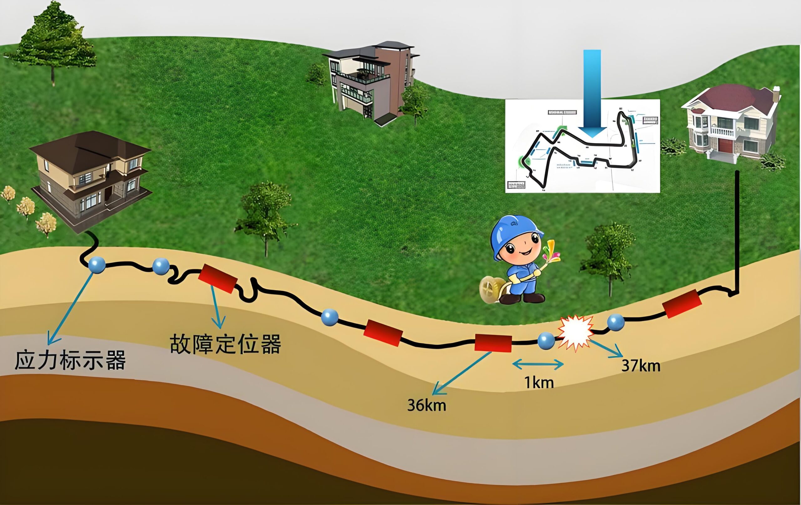
- a. Fault Localization: Before attempting any repair, it is crucial to accurately locate the fault position. This can be achieved using advanced techniques such as Optical Time Domain Reflectometry (OTDR) or visual inspection using fiber optic cable locators or cable tracers.
- b. Cable Preparation: Once the fault location is identified, the damaged cable section needs to be prepared for splicing or repair. This may involve removing the cable sheath, cleaning the fiber ends, and ensuring proper cable management.
- c. Splicing or Repair: Depending on the extent of the damage, the repair process may involve fusion splicing, which involves melting and fusing the two fiber ends together, or mechanical splicing, which uses specialized connectors to join the fiber ends. In cases of extensive damage, a new cable section may need to be installed and spliced into the existing cable run.
- d. Cable Reinstatement: After the repair or splicing process, the cable needs to be properly reinstated. This may involve replacing the cable sheath, securing the cable with appropriate cable management systems, and ensuring proper cable routing and protection.
- e. Testing and Documentation: Once the repair is complete, thorough testing using OTDR and power meter equipment is necessary to ensure the integrity of the repair and confirm signal transmission quality. Detailed documentation of the repair process, including cable routing, splice locations, and test results, is essential for future reference and maintenance.
- Cable Crushing or Deformation Fiber optic cables can also suffer from crushing or deformation, particularly in areas with high traffic or construction activities. These faults can be caused by heavy objects falling on the cable, excessive cable tension, or improper cable installation or routing. Cable crushing or deformation can lead to signal attenuation, increased transmission losses, and potential cable breaks if left unaddressed.
- Repairing these faults typically involves the following steps:
- a. Fault Localization: Similar to cable breaks, fault localization is crucial to identify the affected cable section using OTDR or visual inspection techniques.
- b. Cable Inspection: Once the fault location is identified, the cable should be carefully inspected for any visible signs of deformation or crushing. This may involve removing cable sheath or conduit sections to gain access to the cable.
- c. Cable Replacement or Repair: Depending on the extent of the deformation, the affected cable section may need to be replaced or repaired. In some cases, it may be possible to carefully straighten or reshape the cable to restore its original condition.
- d. Cable Reinstatement: After the repair or replacement, the cable needs to be properly reinstated, secured, and protected from future deformation or crushing.
- e. Testing and Documentation: Comprehensive testing and documentation, similar to cable break repairs, are essential to ensure the integrity of the repair and maintain accurate records.
- Cable Moisture Ingress Moisture ingress is another common fault in fiber optic cables, particularly in underground or outdoor installations. Moisture can enter the cable through damaged sheaths, improper cable terminations, or faulty cable entry points, leading to signal degradation and potential cable damage over time.
- Repairing moisture ingress faults typically involves the following steps:
- a. Fault Localization: Moisture ingress faults can be detected using OTDR or visual inspection techniques, often revealing localized signal attenuation or reflections.
- b. Cable Inspection and Drying: Once the affected cable section is identified, the cable sheath needs to be carefully removed to inspect for moisture ingress. Specialized drying techniques, such as air drying or dehumidification, may be required to remove any moisture present within the cable.
- c. Cable Repair or Replacement: Depending on the extent of the moisture damage, the affected cable section may need to be repaired or replaced. This may involve splicing in a new cable section or applying specialized cable repair kits or moisture-blocking materials.
- d. Cable Reinstatement and Sealing: After the repair or replacement, the cable needs to be properly reinstated and sealed to prevent future moisture ingress. This may involve applying specialized cable entry seals, cable termination kits, or cable sheath repair materials.
- e. Testing and Documentation: As with other cable faults, thorough testing and documentation are essential to ensure the integrity of the repair and maintain accurate records.
- Cable Bend Radius Violations Fiber optic cables have specific bend radius requirements to prevent signal loss and cable damage. Violations of these bend radius requirements can occur during installation, maintenance, or due to improper cable routing or management. Excessive bending or kinking of the cable can lead to increased signal attenuation, potential cable damage, and even complete cable breaks in severe cases.
- Repairing bend radius violations typically involves the following steps:
- a. Fault Localization: Bend radius violations can be detected using OTDR or visual inspection techniques, often revealing localized signal attenuation or reflections at the bend location.
- b. Cable Inspection and Rerouting: Once the affected cable section is identified, the cable needs to be carefully inspected to determine the extent of the bend radius violation. In some cases, the cable may need to be rerouted or re-installed to comply with the recommended bend radius specifications.
- c. Cable Repair or Replacement: If the bend radius violation has caused significant cable damage or signal degradation, the affected cable section may need to be repaired or replaced. This may involve splicing in a new cable section or installing additional cable slack to alleviate the bend radius issue.
- d. Cable Reinstatement and Protection: After the repair or rerouting, the cable needs to be properly reinstated and protected to prevent future bend radius violations. This may involve installing cable management systems, cable guides, or cable wraps to maintain the recommended bend radius.
- e. Testing and Documentation: Comprehensive testing and documentation are essential to ensure the integrity of the repair and maintain accurate records of cable routing and bend radius compliance.
- Fiber Optic Connector Contamination or Damage Fiber optic connectors play a crucial role in optical signal transmission, and their contamination or damage can lead to significant signal loss and communication disruptions. Connector contamination can occur due to dust, dirt, or debris accumulation, while connector damage can result from improper handling, improper mating, or excessive wear and tear.
- Repairing connector faults typically involves the following steps:
- a. Connector Inspection: The first step in addressing connector faults is to visually inspect the connectors using specialized fiber optic microscopes or video inspection probes. This allows for the identification of any contamination, damage, or defects in the connector endface.
- b. Connector Cleaning: If contamination is detected, specialized fiber optic connector cleaners, such as cleaning sticks, swabs, or cassettes, should be used to carefully clean the connector endface. Proper cleaning techniques and materials are essential to avoid damaging the connector or introducing further contamination.
- c. Connector Replacement: In cases of severe connector damage or irreparable contamination, the connector may need to be replaced. This typically involves carefully removing the damaged connector from the cable and installing a new connector using specialized fiber optic termination tools and techniques.
- d. Testing and Documentation: After connector cleaning or replacement, thorough testing using power meters, light sources, or OTDR equipment is necessary to confirm signal transmission quality and ensure the integrity of the repair. Detailed documentation of the connector cleaning or replacement process is also recommended.
Effective maintenance and timely repair of fiber optic cable faults are crucial for ensuring reliable and uninterrupted communication services. Regular cable inspections, adherence to recommended installation and handling practices, and proper documentation can help prevent many cable faults from occurring in the first place.
Additionally, investing in advanced fault localization and testing equipment, as well as providing comprehensive training for technicians, can greatly enhance the efficiency and effectiveness of cable fault repair processes.
By implementing these repair methods and following best practices, communication service providers can minimize downtime, reduce operational costs, and ensure the long-term sustainability and performance of their fiber optic cable infrastructure.